-
Notifications
You must be signed in to change notification settings - Fork 20
RoverAssembly
#Rover Assembly
###Sensors used:
- GPS
- Gyroscopes
- Accelerometers
- Compass
##Connecting your RC
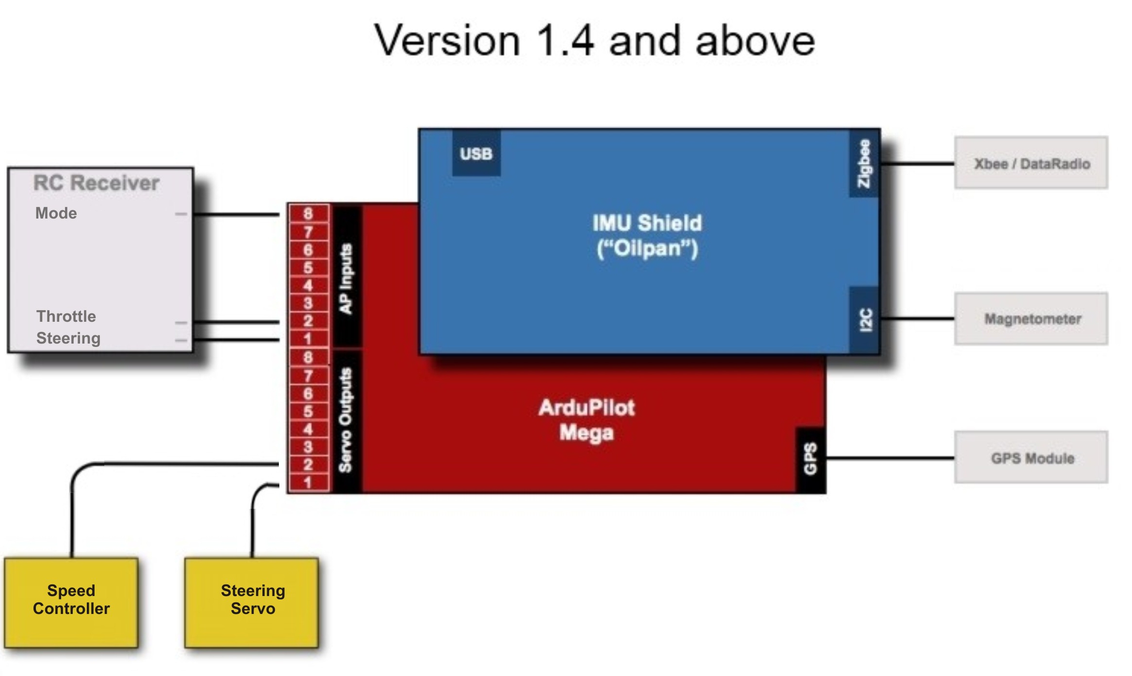
The following diagram shows how to connect your RC components to the ArduPilotMega.

Please note that his setup assumes that your speed controller is able to power the autopilot. Most rovers speed controllers will not supply the necessary current to power the ardupilot, sensors, and steering servos. This will result in brown outs during times of high steering usage. To avoid this problem it is recommended to desolder the SJ1 jumper and use a 7.2 volt (2 cell) lipo battery to power the autopilot.
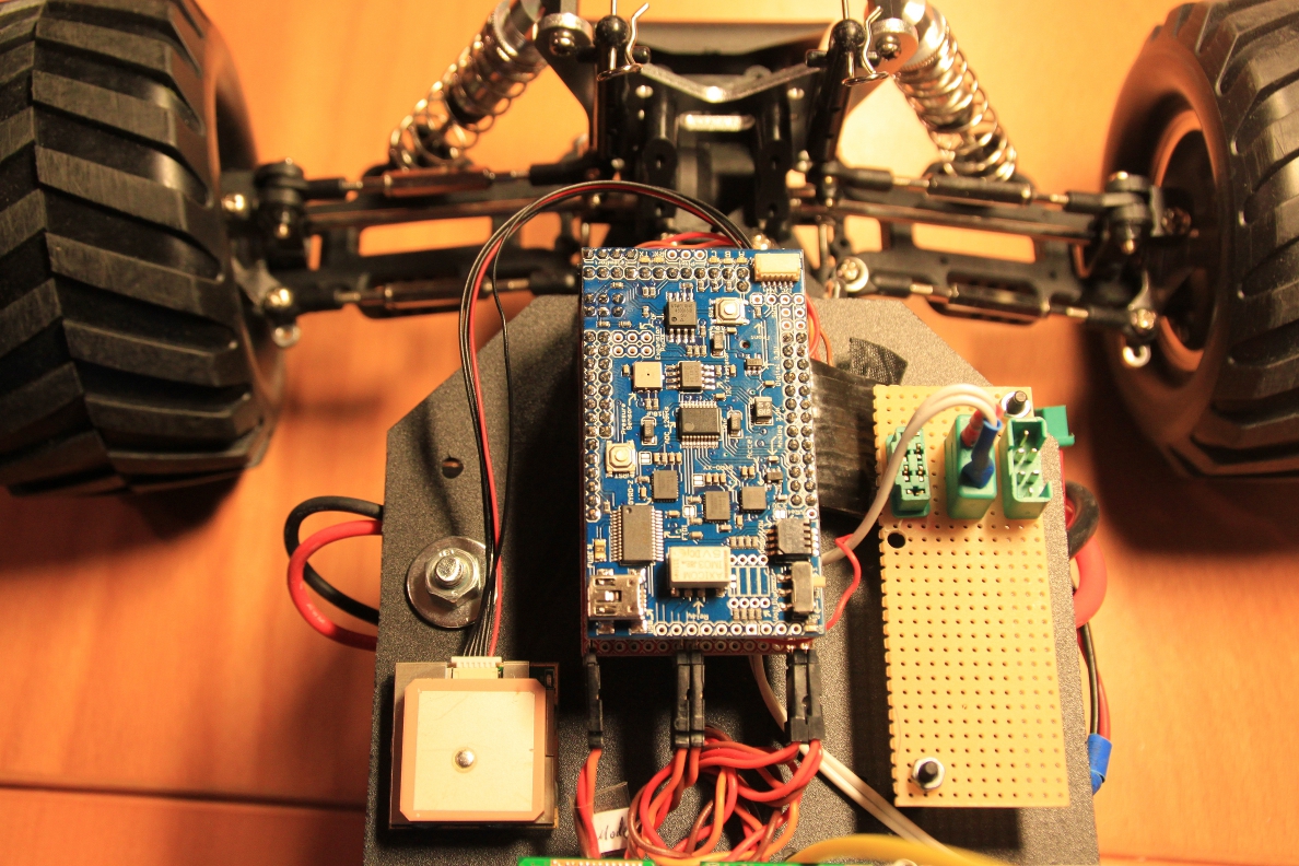
##Component placement and orientation of ArduPilotMega

The picture does not show the compass which usually sits on the I2C-port in the upper left corner. Connected cables from left to right: rc receiver mode channel, rc receiver throttle channel, rc receiver steering channel, output to speed controller, output to steering servo.
