(https://vinaytejab.github.io/Logic-Gate-Simulation/Main%20file/Codes/simulation.html)
A magnitude digital Comparator is a combinational circuit that compares two digital or binary numbers in order to find out whether one binary number is equal, less than or greater than the other binary number. We logically design a circuit for which we will have two inputs one for A and other for B and have three output terminals, one for A > B condition, one for A = B condition and one for A < B condition.

This project is a simulation of the comparators made in Digital Logic Design(DLD). It has only 2-Bit Comparator currently inbuild in the project which can be use for user reference .
A comparator used to compare two bits is called a single bit comparator. It consists of two inputs each for two single bit numbers and three outputs to generate less than, equal to and greater than between two binary numbers.
The truth table for a 1-bit comparator is given below:


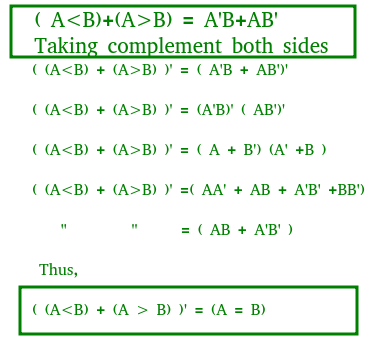
A>B: AB' A<B: A'B A=B: A'B' + AB
By using these Boolean expressions, we can implement a logic circuit for this comparator as given below:
A comparator used to compare two binary numbers each of two bits is called a 2-bit Magnitude comparator. It consists of four inputs and three outputs to generate less than, equal to and greater than between two binary numbers.
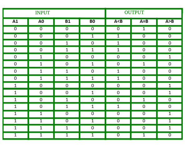


A>B:A1B1’ + A0B1’B0’ + A1A0B0’
A=B: A1’A0’B1’B0’ + A1’A0B1’B0 + A1A0B1B0 + A1A0’B1B0’
: A1’B1’ (A0’B0’ + A0B0) + A1B1 (A0B0 + A0’B0’)
: (A0B0 + A0’B0’) (A1B1 + A1’B1’)
: (A0 Ex-Nor B0) (A1 Ex-Nor B1)
A<B:A1’B1 + A0’B1B0 + A1’A0’B0
By using these Boolean expressions, we can implement a logic circuit for this comparator as given below:

A comparator performing the comparison operation to more than four bits by cascading two or more 4-bit comparators is called cascading comparator. When two comparators are to be cascaded, the outputs of the lower-order comparator are connected to corresponding inputs of the higher-order comparator.

- Comparators are used in central processing units (CPUs) and microcontrollers (MCUs).
- These are used in control applications in which the binary numbers representing physical variables such as temperature, position, etc. are compared with a reference value.
- Comparators are also used as process controllers and for Servo motor control.
- Used in password verification and biometric applications.
- The objective of this experiment is to understand working of the comparator.
- Try to make 2-bit comparator.
- With The help of Theory Page , try to build the Comparator Circuit.
- First of all build the basic 2-bit comparator .
- If You are unable to make it , load the circuit directly and use it.
- If want to see the circuit which you have stored in your system then load it first and continue it make changes to it.
- Use the SAVE button to save it in your system for furture reference.
- HTML
- CSS
- Javascript
The simcir module basically searches for a div with class named "simcir". It reads the json data inside that div, and transforms it into a live simulation.
The json data contains the following things:
- width(integer)- width of the simulator on the screen in px
- height(integer)- height of the simulator in px
- showToolbox(boolean)- decides if the toolbox(the left panel) is to be displayed or not.
- toolbox(array)- items/tools to be shown in toolbox
- devices(array)- devices to be displayed on the breadboard
- connectors(array)- connections between the simulated tools/items.
Input: click Output: page refresh with blank breadboard and interaction enabled(with settings intact).
Test case passed.
Input: click Output: Takes to to help view in a different page.
Test case passed.
Input: click Output:Shows the circuit data in the text box.
Test case passed.
Input: click Output:Inpuits the circuit data from textbox as simulation in the grid.
Test case passed.
Input: click Output:Saves the circuit data after a file name is given into the system.
Test case passed.
Input: click Output: loads the choosen file into the text box.
Test case passed.
Input: click Output:Clears the textbox.
Test case passed.
Input: click Output:Loads the 2-bit comparator into the Simulation place.
Test case passed.
Input: drag/drop/connections Output: everything working correctly.
Test case passed.