Configuration: Night Mode
Switching between night and day mode is controlled by the /sbin/nightmode script, which, when enabled, is run by the cron daemon according to the record in the crontab file:
*/1 * * * * daynight
The nightmode script reads the current gain value from the image sensor and compares it to two threshold values stored in the environment: day_night_max and day_night_min.

The gain value is opposite to the brightness of the scene. It is the amount of gain needed to normalize the image.
If the gain value is below the preset day_night_min and the camera is in night mode, the script activates day mode, or if the gain value is above the preset day_night_max and the camera is in day mode, the script activates night mode.
The daynight script toggles the following three components: infrared illumination, infrared wavelength filter, and color mode as follows:
Day mode:
IR LED is OFF
IR cut filter is ON
Full Color Mode
Night Mode:
IR LED is ON
IR cut filter is OFF
Black & White Mode
Each of the three components can be controlled separately by its own script.
The daynight script toggles multiple components at once. You can choose which parameters to leave unchanged.
For example, a camera placed behind a window will be blinded by IR LEDs reflecting off the glass, so you may want to uncheck the IR LED options in the form below.

The camera can have several illumination groups: IR LEDs of different wavelengths and/or white light LED. Infrared light of 850 nm can be seen with the naked eye, 940 nm is not seen by most people, but you can see it with a cell phone camera.

irled controls the infrared illumination (IR LED) by setting a corresponding GPIO pin to a high or low state. Different cameras can have different schematics, and the LED can be activated either in high pin state or in low pin state. The correct control variant can be set in the form above with the active low checkbox for pins that activate the lighting in low state. If you want the lighting group to be active on boot, check the lit on boot checkbox and save the form.
To disable a lighting group, clear the pin value of the group and save the form.
IR Cut is a mechanical infrared filter placed between the camera lens and the image sensor to eliminate infrared light waves.

Infrared light waves while invisible to the naked eye, can interfere with the captured image. Infrared rays cause the image to take on a reddish-purple hue.

The filter blocks a specific wavelength of light that passes through the lens, resulting in an image that closely resembles what we see with our eyes.

Although infrared rays are abundant and inconvenient during the day, they are still present at night when reflected from the moon and can help the camera capture better images in low-light conditions. To facilitate this, infrared rays must pass through the sensor when the amount of visible light is insufficient. An infrared filter switcher, a mechanical device that uses electromagnetic force to move the filter in front of or away from the image sensor, can accomplish this.
There are at least two types of sliding mechanisms for moving the filter: a drawer type where the filter moves forward and backward, and a swing type where the filter rotates around a pivot point.
A standard IR cut filter switcher designed for an IP camera operates on a voltage range of 3.3V to 5V DC and sends short pulses of 50 to 100 ms.
The switcher is connected to the board via two wires and reverses direction based on polarity. GPIO pins control the polarity, so it is important to configure the correct pins in the camera settings.
An example of controlling the direction of a switcher with two GPIO pins:
 ------------- ------ ------ ------ ------
| GPIO 25     | LOW  | HIGH | HIGH | LOW  |
| GPIO 26     | LOW  | LOW  | HIGH | HIGH |
|-------------+------+------+------+------|
| IRCUT PINS  |  0V  |  +5V |   0V |  -5V |
 ------------- ------ ------ ------ ------
GPIO pins are set in the form below:

The voltage applied to the switch is controlled by the opposite states of the GPIO pins. The driver solenoid is a physically robust but electrically fragile component that converts energy into motion. If the solenoid does not convert energy into motion, it will generate heat and may overheat or even burn.

It is critical to remove power from the solenoid when it has completed its task by setting both GPIO pins to either a high or low state.
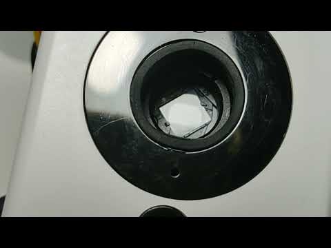
The ircut script toggles the position of the IR cut filter. Run ircut on to apply the filter and ircut off to remove it.
Demonstration of an IRcut filter in action
When the scene is illuminated by infrared light, everything takes on a purple hue. Switching the camera to a monochrome black-and-white mode will help eliminate the hue and increase the contrast of the image.
Run color on to switch the camera to full color mode and color off to monochrome black and white mode.
Your IRCUT filter maybe controlled in reverse. To check the camera's IRCUT mode. Point the camera at a reflective surface. Run ircut on; irled on in the console. You should see slightly visible IR LEDs on the camera.

If, instead, you see brightly glowing IR LEDs, the order of your IR cut filter pins in the environment needs to be reversed.

Read the values from the environment and then save them in the reverse order as shown below.
[root@wyze-v3-test ~]# fw_printenv -n gpio_ircut
25 26
[root@wyze-v3-test ~]# fw_setenv gpio_ircut 26 25