FAQ
- Make sure that you are measuring the right pin.
- Test if you get a signal when setting the mode to ON. (In Micromanager, mode = 1)
- If the ON/OFF modes are working but not the other modes, check that duration is not 0 (and large enough to be detected) for RISING/FALLING modes and that sequence is equal to 65535 (or 1111111111111111 in binary).
- Verify that the camera signal is a square trigger pattern.
The Mojo cannot drive too many servos at the same time. Servos need three inputs: power, ground and signal. In particular, large servos will not work properly if the supplied power is smaller than 5V, which is the case of the Mojo (3.3V). Therefore:
- If you need to drive (= supply the power) several servos with the Mojo, consider using an additional power supply to the Mojo.
- If you need to drive a large servo, use the RAW pin on the Mojo, which supplies 5V.
- Consider driving the servo with an external source, while using the Mojo servo output as the servo signals. (do not forget to link the ground).
Example (the error might be different):
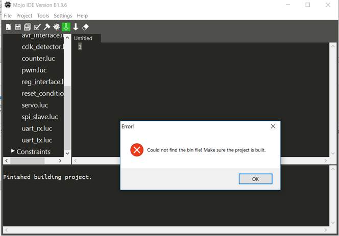
Such error can arise due to the discontinuation of ISE support (Xilinx) for Windows version later than 7. Please refer to Installing ISE for some workarounds.
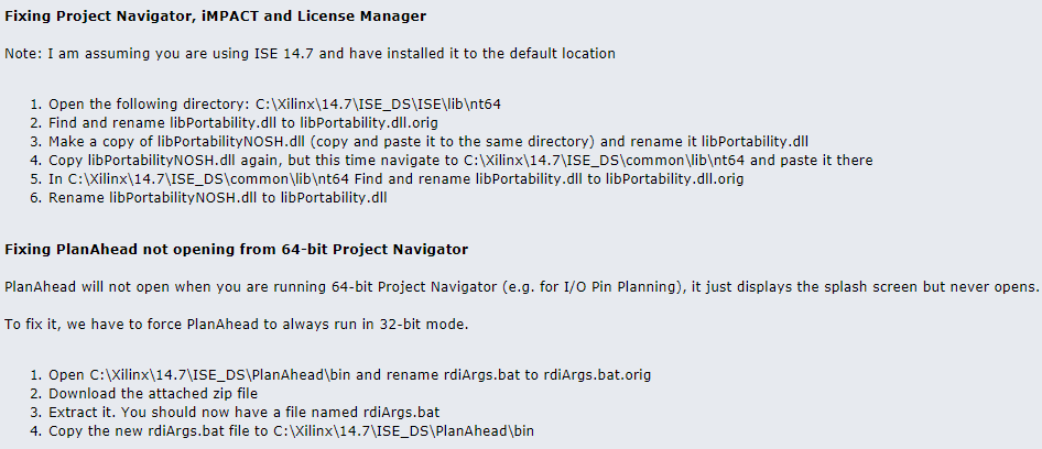
In the case of Windows 8 and 10 (64 bits), you might need to refer to this page, and in particular:
- Fixing Project Navigator, iMPACT and License Manager
- Fixing PlanAhead not opening from 64-bit Project Navigator
Solution by BytesGuy on www.eevblog.com/forum
I use the PWM output with a low-pass filter to produce an analog signal, but the device seems to not work to its full capacity.
If the device expects a 0-5V analog signal, then the 3.3V of the Mojo might not be enough, make sure that after the low-pass filter, the signal goes from 0-5V.
My device has a TTL input trigger but it does not reach its full capacity when triggering with the Mojo (Laser, PWM...)
See previous point.
Except for the analog read-out pins, every signal's pin can be channeled to a different pin. Open the MicroMojo/Firmware/constraint/user.ucf file and modify the pin number. You will then need to recompile the Lucid code and upload it to the mojo.
(to be described)
(to be described)