I wanted to explore / investigate some IoT style coding for low level sensors. After talking to a few people I purchased a Rapberry Pi 4 and was given to experiment with a LoLin32 Lite micro controller board along with a BMP280 temperature. humidy, and pressure sensor. Specific details of what I have are:
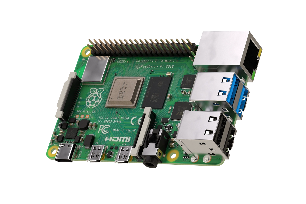
- A Raspberyy Pi B 4GB starter kit which included a case, cables, power supply, SD card etc. But a plain Pi would work for this example.
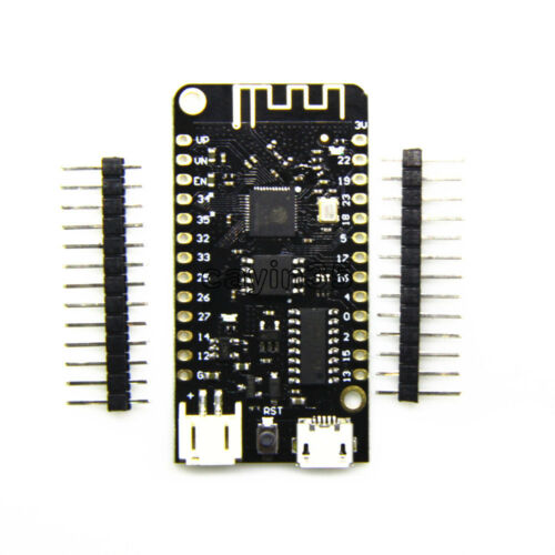
- A LoLin32 Lite microcontroller board - similar to this
- A Bosch BME280 temperature, humidity and pressure sensor similar to this On the back of the chip it has a chip type of GYBMEP.
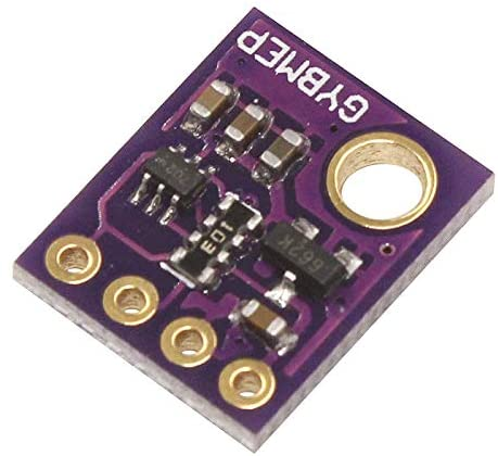 The specific details and data sheet for this can be found here
Other chip sets and boards are available but I wanted to list exactly what I had and tried.
As this was my first venture into the Raspberry Pi and also the microcontroller boards I searched the web and found a very good artilce titled Unpacking the Wemos ESP32 Lolin32 Lite, testing the firmware MicroPython with a Raspberry Pi 3. Although it was for a Raspberry 3 I was gambling on it working for the Pi 4 B, which it seems to do.
The first thing to do was to connect the board to the Pi via a USB cable and then check for detection of the board via
dmesg | grep ttyUSB
however I found that I could not detect the board after trying 3 or 4 cables. I went back to the person who loaned me the board and they tried with their linux box again, they too found that it worked with some cables and not others. Once I had a working cable the Pi detected the board and could connect over ttyUSB0. I have not got to the bottom of which cabcles work and why others do not.
Within the article the first python scripts turns an led on and off but I did not have an led to try. I did find out that there is an inbuilt led on pin 22 so the very first piece of python I tried was:
import utime
    import machine
    pin22 = machine.Pin(22, machine.Pin.OUT)
    while True:
        pin22.value(1)
        utime.sleep_ms(500)
        pin22.value(0)
        utime.sleep_ms(500)
After many days searching the web for details on how to drive the sensor in python I came across the following useful article that pointed me to some great python code which did not need many changes. MicroPython: Send Sensor Readings via Email (IFTTT) with ESP32 and ESP8266
The figure below shows the BME280 sensor and its pinout.
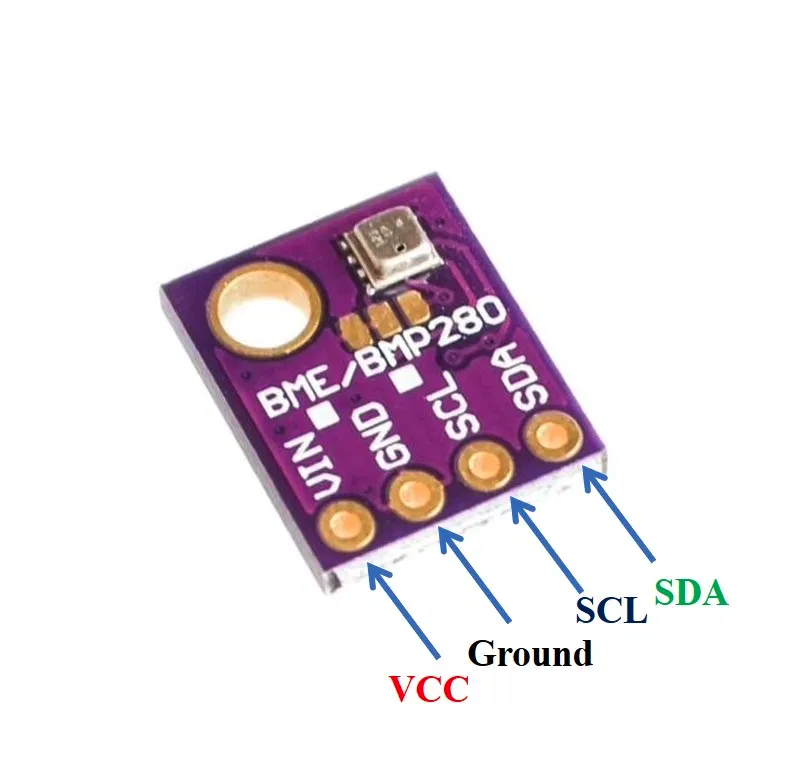
- VCC: connected with 3.3V
- SCL: used to generate the clock signal
- SDA: used in sending and receiving data
This took quite some investigations as I was not familiar with the board, nor a lot of the terminology and the fact that most articles referred to the ESP32 or ESP8266 boards.
I found a schematic for the board pinouts as:
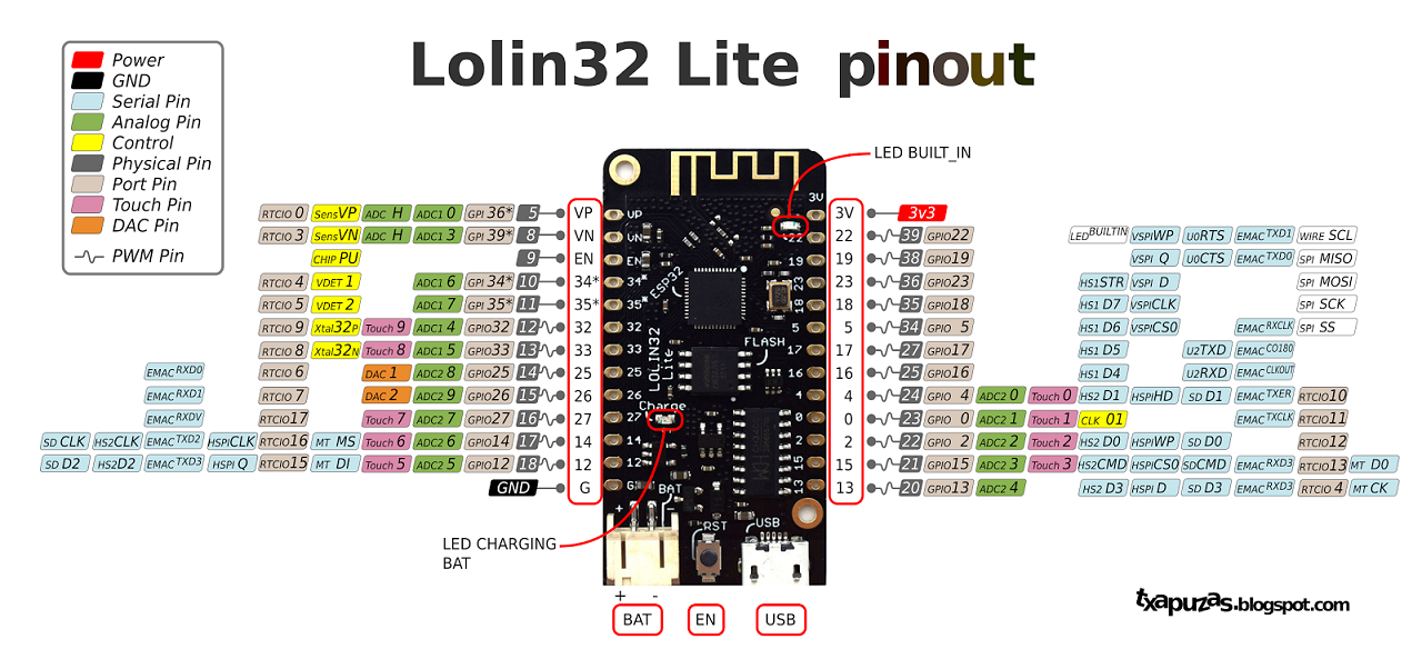
so connecting the ground and the voltage was quite easy. The next stage was which pins to connect the SDA and SCL to. From the article it did not state the pins to use for the LoLin32 Lite SDA,SCL and so I did a further search locating this article LOLIN32 Lite with I2C SSD1306 OLED 128×64 which describes how to use the I2C data transfer mechanism. According to the article the SCL should be connected to Pin 4 and SDA connected to Pin 0.
See Photo of my board connections: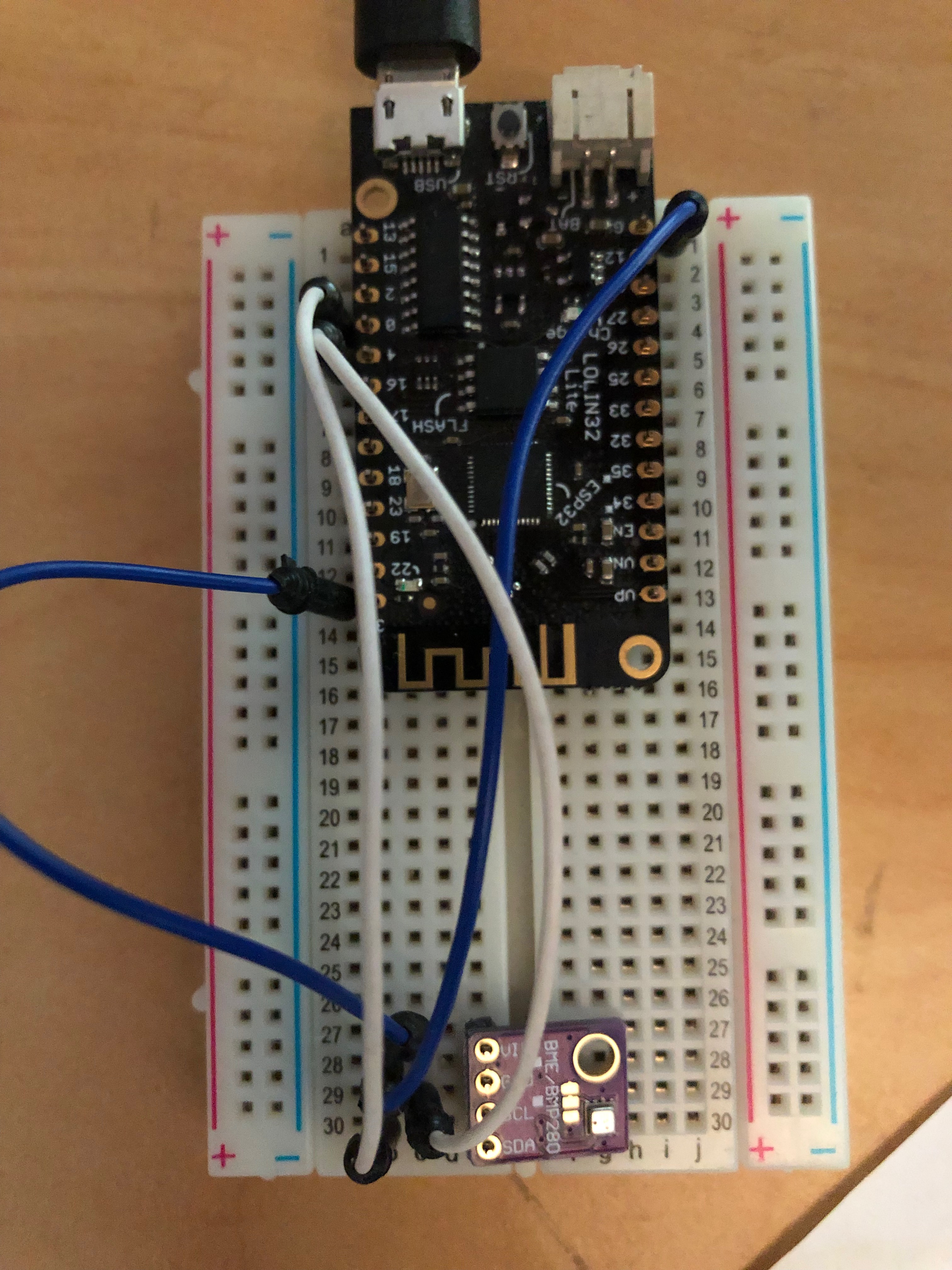
From the above article on Send Sensor Readings... there is a link to a driver which I have taken a snapshot copy of and added it to the src directory. I then copied the python file to the /pyboard folder on the microcontroller. I then main the following chnages to the main.py run file that REPL uses when a control-D is pressed. I have also added this file to the src directory.
main.py
print('Running in main.py')

from machine import Pin, I2C
from BME280 import BME280

i2c = I2C(scl=Pin(4), sda=Pin(0), freq=10000)
bme280 = BME280(i2c=i2c)
bme280.values

print( "Values were printed")