Instructions for older board versions are available at the relevant tag
Buy a kit on my website or Follow me on instagram for updates
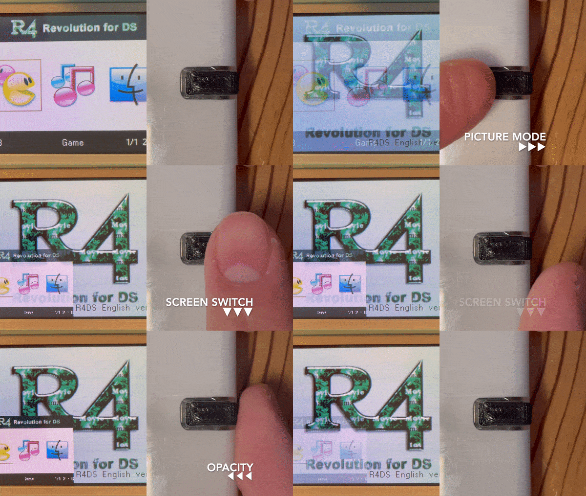
A screen switch breakout board for the DS Lite / GB Macro - requires the TV Out Firmware Mod by LostNintendoHistory Lost-NDS-TV
- The components used should be available in the BOM.csv file.
- I ordered boards with the bottom half populated from jlcpcb using the gerber, bom and, pick and place files, then soldered on the switches myself.
- The flex cable I use is a 25 pin 0.3mm pitch 120mm long ffc which i sourced from aliexpress
You need to flash your ds lite with the tv out firmware mod or buy a kit - I recommend following facelesstech's guide as he has gathered the most relevant information in one place.
- This mod requires the macro mod, this involves soldering a 330r resistor across LEDA2 and LEDC2
- After removing the stylus tray, The 3D printed button cap can be put in place from inside of the enclosure.
- Use two of the original stylus tray screws (ones with the slight gold tint) to secure the breakout board on top of the cap. v1.0 video example
- If your buttons are not clicking, back off one or both of the mounting screws a tiny bit to adjust.
- If soldering follow this pin out
- I found that running wires underneath the ds game card slot is a good route for this.
- If installing using the flex cable it must be plugged in to right hand side of the top screen connector nearest pin 1, as pictured:
- You will need to allow the flex cable to fold somewhere underneath the battery.
- Due to only using ~half of the top screen port it is possible to missalign the flex cable and the swtiches won't work - if this is the case - try again but ensure the flex cable is as far as it can go in to the port and to the right of the port.


