Board Assembly Instructions
Here are some tips on assembling the z80ctrl board for the RC2014.
The z80ctrl board is designed as a plug-in module for the RC2014 retrocomputer kit.
z80ctrl requires a backplane with an extended RC2014 bus:
- RC2014 Backplane Pro (12 slots)
- SC112 6 Slot Backplane
- SC116 3 Slot Backplane
- SC113 6 Slot Backplane Extension
- 40 pin backplanes will not work because they lack the required signals.
The only other requirements are a Z80 CPU and RAM. It's compatible with the following RAM and CPU boards:
- The companion Z80 CPU/RAM/RTC board board is recommended for use with the z80ctrl.
-
Z80 CPU v2.1 board will also work when combined with one of the following:
- 64K RAM board. The jumpers should be configured for a RAM start address of 0000H.
- 512K RomWBW board. z80ctrl supports flashing the ROM in this board, but the ROM is not used by z80ctrl and can cause some minor compatibility issues with some software.
Note: the clock, serial, rom, and CF boards normally used in an RC2014 are not compatible with z80ctrl.
- Complete Kits are available on Tindie for both z80ctrl and the CPU/RAM/RTC board. These include the PCB and all necessary components.
- Gerbers are available on Hackaday. I highly recommend JLCPCB for PCB fabrication. You can also order PCBs directly on OSH Park if you prefer.
- A bill of materials is available for either REV4 or REV6 Note that the part numbers for passive components are furnished as a convenience and other parts with similar values will usually work. The CSV can be uploaded to Digi-Key or Mouser to add the items directly to your cart.
- The Pololu SD Breakout is preferred, but z80ctrl also supports the Adafruit SD Breakout. Digi-Key carries both but Mouser only carries the Adafruit board.
- Tayda Electronics is a cheap source for commodity components (resistors, capacitors, header pins, etc.), but they do not carry the chips used by the z80ctrl. Tayda part numbers are also listed in the BOM where applicable.
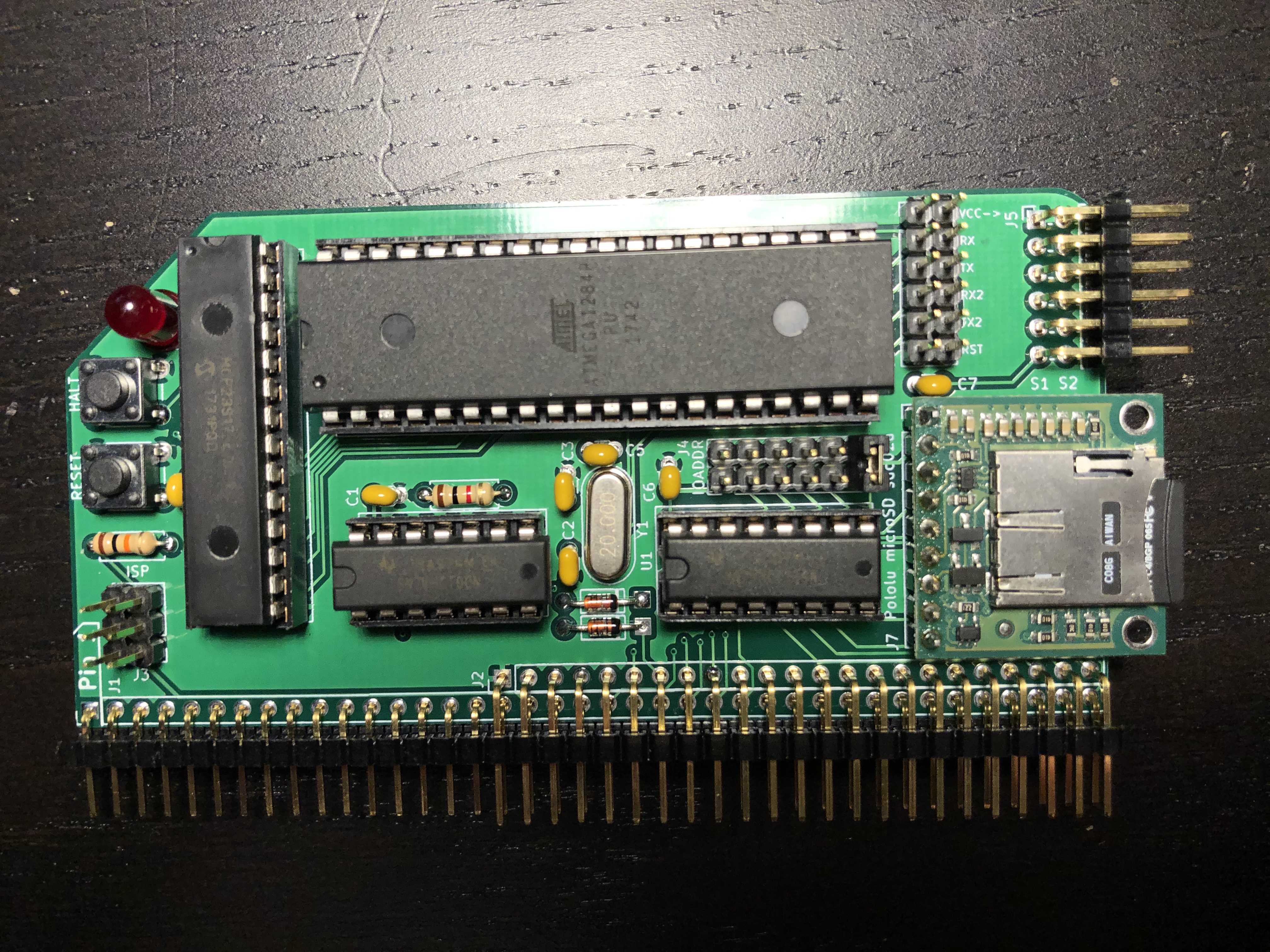
- Refer to the pictures, bill of materials, and schematics for your revision to match parts to their labels on the PCB.
- Insert and solder the components in order from shortest to tallest: diodes, resistors, capacitors, crystal, buttons, sockets, SD breakout, angled pin headers, LED, and finally straight pin headers.
- Important: on REV6 boards make sure you install the resistors beneath the SD breakout before you solder it in place. You will not be able to reach them after the SD breakout has been soldered in place. This does not apply to REV4.
- If using the Adafruit SD breakout, be sure to put it into the right row of holes on the board. It will fit into the space for the Pololu breakout but the pinout won't match.
- For LED D2, the cathode (short leg) should go into the square pad.
- Check the hardware issues page for a list of known problems and their fixes.
- If you run into trouble, search for z80ctrl on the RC2014 Google Group, and if you don't find a solution to your problem, feel free to ask.
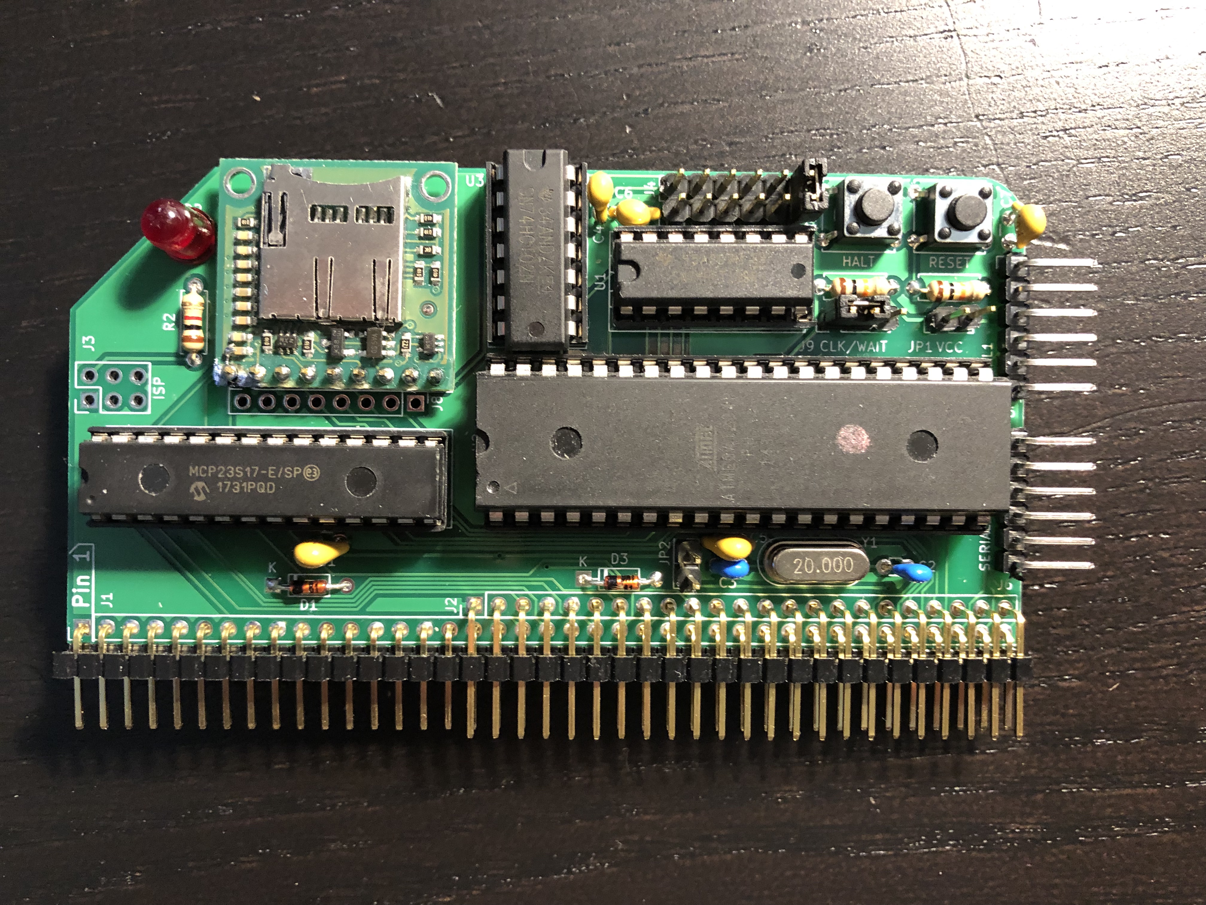
- J9 (CLK/WAIT) jumper should be shorted in the CLK (left) position. The WAIT (right) position is intended to allow the z80ctrl to work with an external clock source but software support for this has not been written yet.
- J4 (IO WAIT ADDR) jumper should be shorted in the far right position (all addresses). Other settings will not work correctly in REV3 or REV4 (see known issues). If you get stuck in an endless loop when you boot CP/M, double-check this jumper.
- JP1 (VCC) can be shorted to provide power from your USB-to-serial adapter for initial programming and testing of the board. It should not be used to power the entire RC2014. The jumper should be removed before the z80ctrl card is inserted in the backplane.
- JP2 can be shorted to export the reset signal to the D15 line on the RC2014 bus so that any I/O expanders will be reset at the same time as the AVR. This line is normally unused in the RC2014, so it is usually safe to repurpose.
- J3 is an ISP header for programming the AVR. It should not have any jumper blocks on it.
Note: on REV3/REV4 the silkscreen on the back of the board incorrectly identifies JP2 as VCC from SERIAL2.
- J4 (IO WAIT ADDR) allows you to select which range of IO addresses z80ctrl will respond to (None, 00-3FH, 40-7FH, 80-BFH, C0-FFH, or All). The emulated UART and disk drives are in the first range, so you will normally want to set this to the second position (00-3FH) or the last position (All).
- J6 (Link) jumpers allow selectively connecting signals to the bus. The signals are labeled next to the jumper on the board.
- VCC can be connected to provide power from your USB-to-serial adapter for initial programming and testing of the board. It should not be used to power the entire RC2014. The jumper should be removed before the z80ctrl card is inserted in the backplane.
- The reset signal can be connected to the D15 line on the RC2014 bus so that any I/O expanders will be reset at the same time as the AVR. This line is normally unused in the RC2014, so it is usually safe to repurpose.
- The RX/TX and RX2/TX2 signals can be connected to the bus. You probably want to do this if you want to use the z80ctrl with the ESP8266 Wi-Fi board or a VGA or Raspberry Pi terminal board. However, you should disconnect them if you have any other UART boards installed in your system.
- J3 is an ISP header for programming the AVR. It should not have any jumper blocks on it.
- Note: AVRs provided in the kits come with the bootloader already installed.
- If you source your own AVR, I highly recommend programming it with the MightyCore bootloader so that z80ctrl can be updated over the serial port.
- The easiest way to flash the bootloader is using a stand-alone AVR programmer and the Arduino IDE. Follow the MightyCore instructions. Make sure you select the following options in the tools menu:
- Board: "ATmega1284"
- Pinout: "Standard"
- Clock: "20 MHz external"
- Compiler LTO: "Disabled (default)"
- Variant: "1284P"
- BOD: "2.7v"
- Port: (the correct port for your ISP)
- Programmer: (the type of ISP you are using)
- If you flash the bootloader some other way:
- Use the optiboot_flash_atmega1284p_UART0_115200_20000000L_B0_BIGBOOT.hex bootloader image
- Set your fuses to 0xf7 (low), 0xd6 (high), 0xfd (extended).
- For programmers that specify fuse bits individually, fuses named CKSEL3, SPIEN, EESAVE, BOOTRST, and BODLEVEL1 bits should be programmed. All others should be unprogrammed.
You will need to obtain the command-line AVR toolchain to build the firmware:
-
Windows: Download the AVR toolchain for Windows. This includes all necessary tools. Do not use WinAVR; it has not been updated since 2010 and will not build z80ctrl correctly. Once extracted, the avr-gcc bin (for example
c:\avr-gcc-11.1.0-x64-windows\bin), directory should be added to your path. You do not need to follow AVR-GCC instructions for upgrading the Arduino IDE because z80ctrl's build process doesn't use the Arduino IDE. - Linux (or Windows Subsystem for Linux): Install gcc-avr, avr-libc, avrdude, and make packages from your package manager.
- Mac OS X: Use the homebrew-avr formulae to install via Homebrew. Also install the avrdude package.
- Clone the repo using
git clone https://github.com/jblang/z80ctrl/or download a zip of master. The code is located in thefirmwaresubdirectory. - You will need to edit the
Makefileto uncomment and change the configuration options:- At a minimum, you must set
BOARD_REVto match your hardware revision. Only REV3 and greater is supported by the latest firmware. - Set the
PORTvariable to match the serial port that your USB-to-Serial adapter uses. On Windows this will beCOMn; on Linux, it will be/dev/ttySn; On Mac, it will be something like/dev/cu.usbserialor similar. Be aware that the COM port may change if you plug the adapter into a different USB port. - If you want RAM paging support, set
PAGE_BASEto the base address of your RAM/ROM board's paging register. This requires REV3 or later hardware. - If you want support for writing SST flash ROMs, uncomment
SST_FLASH=1. This requires paging support and REV3 or later hardware. - If you want support for the TMS9918A chip, set
TMS_BASEto the base address of your chip. This requires z80ctrl REV3 or later and a TMS9918A board. - Additional configuration options may have been added since this was written. Read the comments in the Makefile.
- At a minimum, you must set
- Connect the SERIAL1 header to a USB serial adapter, making sure that the GND wire is on top. Run
make installin the repo directory. If you change any options in the Makefile after building z80ctrl, you must runmake cleanfirst to guarantee that the changes take effect. - If all goes well, your z80ctrl board should now be functional. Connect a terminal to the correct serial port at 115200, and you should be greeted with a
z80ctrl>prompt.
- Format an SD card as FAT32. Copy the hello.hex file to it. Put the card in your z80ctrl board and reset it. Type
dirto confirm that it can read the card. If so, runloadhex hello.hexand thenrun 100. If everything is working correctly,hello, worldwill be printed out. - Refer to the user's guide for an in-depth tutorial on the z80ctrl monitor interface.