-
Notifications
You must be signed in to change notification settings - Fork 16
OptoShield
Introduction
Application programming interface
C/C++ API
Simulink API
Examples
System identification
PID control
Detailed hardware description
Circuit design
Parts
PCB
About
Authors
The OptoShield belongs to the family of control engineering education devices for Arduino that form a part of the AutomationShield project. This particular low-cost shield contains a simple circuitry implementing a light emitting diode (LED) as the actuator and a light-dependent resistor (LDR) as a sensor. The LED and LDR are enclosed in an opaque tube that blocks ambient light. The power of the LED can be varied by applying a pulse width modulated (PWM) signal to it, thus manipulating its apparent brightness. The LED and LDR thus creates a simple feedback loop that can be used in control engineering experiments.
Before you proceed, you may also want to watch a short video tutorial here.

The basic application programming interface (API) serving the device is written in C/C++ and is integrated into the open-source AutomationShield Arduino library. This library contains hardware drivers and sample exercises for control systems engineering education. The OptoShield API is located in the OptoShield.h header and a corresponding source file; these implement the OptoClass class which is then declared as default OptoShield instance. The functions specific to this shield mostly perform input/output peripheral communication. Certain library functions are common to all of our shields and are included in the AutomationShield class.
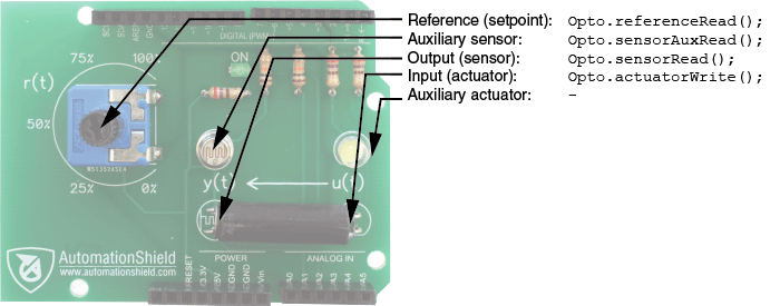
The summary of functions and the illustration below should get you started quickly:
- Output (sensor):
Opto.sensorRead(); - Input (actuator):
Opto.actuatorWrite(); - Reference (setpoint):
Opto.referenceRead();

The following sections describe the methods used to access the input and output of the OptoShield. Note that before you begin an experiment you must initialize the hardware by calling
OptoShield.begin();
which determines the mode of the input and output pins.
This must be followed by
OptoShield.calibrate();
to re-scale the input and output values.
Because the LDR cannot measure physically valid units, the signal to the LED and from the LDR will be given in percents of the full scale. The method calibrated() thus finds the minimal and maximal analog-to-digital converter (ADC) levels measured at the sensor. The returnCalibrated() method returns a flag informing on the calibration state, while the returnMinVal() and returnMaxVal() method return the sensor calibration levels.
The input to both actuator LED an auxiliary LED is written by calling the method
OptoShield.actuatorWrite(u);
which accepts input u as a floating-point number in the range of 0-100 %. This will send a PWM signal to both LEDs. The behavior of the visible LED is mirrored in the one located in the tube.
The output from the LDR is read by calling
y = OptoShield.sensorRead();
which returns a floating-point number in the calibrated range of 0-100 % representing process output y. The voltage at the main sensor is accessible through the sensorReadVoltage() method as well, while the auxiliary sensor can be accessed via sensorAuxRead().
The onboard potentiometer can be used in any role, but the most straightforward one is to read a user-defined setpoint r using
r = OptoShield.referenceRead();
which returns a floating-point number between 0-100%.
If you cannot program in C/C++ just yet, you may want to try out the Simulink API for the OptoShield that enables to create control loops and perform live experiments in the Simulink environment. It utilizes the Simulink Support Package for Arduino Hardware which supplies algorithmic units in blocks that access the hardware functionality. The block scheme in Simulink is transcribed into C/C++, then compiled to machine code and uploaded to the microcontroller unit (MCU). In other words, code is run directly on the microcontroller. Simulink not only transcribes the block schemes for hardware, it also maintains the connection between the development computer and MCU. This way controllers can be fine-tuned in a live session, or data may be displayed and logged conveniently.
The Simulink API offers the following algorithmic blocks:

The 'Actuator Write' block accepts real numbers from 0-100% and supplies power to the onboard LEDs.
The 'Sensor Read' and 'Sensor Aux. Read' blocks read the input from the LDR and its auxiliary twin, respectively. User may select the desired type of outputs such as voltage, ADC levels or a manually calibrated signal in percentages. The onboard potentiometer may be accessed in a similar fashion using the 'Reference Read' block.
The 'OptoShield' block unites the input and output functionality into a single entity that can be conveniently used for identification and control experiments. The block automatically calibrates the sensor to the available range, then accepts a saturated input signal in the range of 0-100 % and reads the calibrated brightness signal from the main LDR. One may also use the 'OptoShield TF' block to model the process dynamics by a continuous linear transfer function for simulation-only exercises.
Input-output experiments for data gathering can be launched, displayed and logged in C/C++ (Arduino IDE) and Simulink as well. The AutomationShield library for OptoShield incorporates several worked examples. For example, one worked C/C++ example illustrates the input-output step response of the onboard optical system. A more detailed example runs through a pre-set array of open-loop inputs, incorporates an interrupt-based sampling system and lists the results to the serial communication line. The dynamic response of the system can be followed through the built-in Serial Plotter of the Arduino IDE. This enables one to display the process dynamics within the development environment itself.

The results can be also listed using the Arduino Serial Monitor or even logged by a number of third party applications, then exported to other software for visualization and post-processing.
Apart from this simple graphical representation, the library includes a MATLAB function to read the results to the MATLAB workspace and plot them. The figure below shows the input and output data gathered through the latter example.

The collected data can be readily used to perform system identification procedures. Using another MATLAB function one may identify a continuous-time first-order process model using the MATLAB's System Identification Toolbox and compare the model to the measurement results. As a result, the first-order transfer function
produces a ∼96.5% match with measurement data, as long as we compare a unit step from zero level up to the expected working range of the optical tunnel.
By inspecting the response it is however clear that this simplified dynamic representation is far from perfect, as the real process demonstrates hysteresis and significant nonlinearity. One may therefore attempt to create models compensating for these effects as well.
Similarly, a worked Simulink example performs a simple step change of input, displays the progress of the response live on screen and saves a data file.
For a start you may want to experiment with a closed-loop control of the LED brightness using the well-known proportional–integral–derivative controller (PID) algorithm.
The PID control examples included within the library contain an example with manual reference levels set through the potentiometer and an example with pre-determined setpoints. The example code initializes the board and by calling the generic AutomationShield.h header also makes use of the sampling and PID functionality of the library. Discrete sampling is realized by launching an interrupt-enabled callback routine at each sampling period. You may be also program your own PID routines, or alternatively, the library contains PID algorithms in both absolute and incremental forms with integral wind-up and saturation limits.

Shown above is a PID controlled closed-loop experiment, where the algorithm was tuned to
,
and
. Despite the true hysteretic an nonlinear nature of the process the PID algorithm handles feedback control quite well. Note that the output oscillates around the setpoint—especially at lower reference levels—because the LED is powered by a PWM signal instead of a stable true analog input from a digital-to-analog converter (DAC).
The same feedback control loop can be built even easier using the Simulink API. Shown below is the full block scheme for discrete saturated PID control of the process. You need only to select the 'OptoShield' block from the API library to implement the input/output of the hardware. Other blocks, such as the 'Discrete PID Controller', can be readily selected from the Simulink's default library.

After selecting the External running mode the block scheme is re-interpreted to C/C++ code, which is then compiled to AVR-specific machine code and downloaded to the MCU, while two-way communication is preserved between the block scheme and the hardware. You may use switches, sliders and knobs to select reference levels and inspect the response live using a 'Scope'.

The OptoShield is an open hardware product, you are free to make your own device. If you come up with improvements, please let us know so we can improve our design as well. The discussion below should help you to improvise a similar setup for experimentation on a breadboard or perforation board. You may even order a professionally made PCB by a PCB fabrication service.
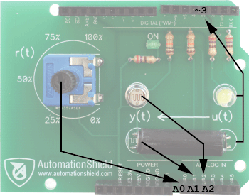
For those who wish to use the board without the library, the components are connected to the following pins:

The circuit schematics has been designed in the Freeware version of the DIPTrace CAD software. You may download the circuit schematics for the OptoShield from here.

The current to both the main LED D1 and its external duplicate D2 is limited by series resistors R3 and R4. The value of these resistors has been chosen so as to create a maximum brightness that is within the sensing range of the LDR. Both LED are connected to digital output D3 of the MCU, therefore the brightness of the external LED copies that of the main one.
The main LDR acting as a sensor LDR1 is connected to the A1 analog input of the MCU through a voltage divider configuration using resistor R1. Its value has been chosen to increase the resolution at the output measurement when combined with the brightness of the LED. This is repeated for the external sensor with LDR2 and R2 connected to the input A2. Finally, the potentiometer is connected to the A0 input of the MCU, while the power LED with its series resistor is omitted from the scheme.
To make an OptoShield either on a PCB or on a breadboard you will need the following parts or their similar equivalents:
| Part | Name | Type/Value/Note | PCS |
|---|---|---|---|
| LDR1,LDR2 | Photoresistor | 5-10kΩ, 5mm | 2 |
| D1,D2 | LED | 5mm, clear | 2 |
| POT1 | Potentiometer | 10kΩ, pin size 12.5x10 | 1 |
| R1,R2 | Resistor | 2.4kΩ | 2 |
| R3,R4 | Resistor | 4.7kΩ | 2 |
| - | Header | 10x1, female, long, stackable | 1 |
| - | Header | 8x1, female, long, stackable | 2 |
| - | Header | 6x1, female, long, stackable | 1 |
| - | Tube | 20mm, Ø5mm, opaque | 1 |
Note that the total cost of the above components, including the PCB, and thus of the entire OptoShield is less than $3 excluding labor and postage.
The printed circuit board has been designed in the Freeware version of the DIPTrace CAD software. The PCB is two-layer and fits within the customary 100x100 mm limit of most board manufacturers. The DIPTrace PCB layout and circuit schematics can be downloaded here and here, respectively, while the ready-to-manufacture Gerber files with the NC drilling instructions are available from here.


This shield was designed and created within the framework of a Bachelor's thesis at the Institute of Automation, Measurement and Applied Informatics in 2017/2018. The Institute belongs to the Faculty of Mechanical Engineering (FME), Slovak University of Technology in Bratislava.
- Hardware design: Tibor Konkoly, Martin Gulan, Gergely Takács
- Software design: Tibor Konkoly, Gergely Takács
- Wiki: Martin Gulan, Erik Mikuláš and Gergely Takács

Takács et al., 2018-2023. The hardware design, software and manual featured in this repository is licensed under a Attribution-NonCommercial-NoDerivatives 4.0 International (CC BY-NC-ND 4.0). Please consider citing our work in your publication.
