
A high-performance implementation of the I2C (Inter-Integrated Circuit) protocol bridging a Raspberry Pi Pico (Master) and an Arduino (Slave). This setup features dual-bus hardware isolation to optimize telemetry data flow across cross-platform architectures.
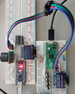
The goal was to establish a deterministic Controller-Target communication link between different hardware architectures. While I2C supports multi-mastering, practical implementation often leads to clock-synchronization errors on the SCL line and bus arbitration overhead.
This project solves these issues by using the RP2040 as a centralized hub. The primary technical hurdle overcome was bridging the MicroPython environment (which lacks native I2C Slave support) with the C++ (Wire.h) environment on the ATmega328P.
- Cross-Platform Bridge: Seamless data serialization between MicroPython (Master) and C++ (Slave).
- Dual-Bus Isolation: Utilizing both I2C0 and I2C1 hardware controllers on the RP2040 to separate high-bandwidth display traffic from time-critical sensor data.
- ISR-Driven Telemetry: Arduino utilizes
onRequestInterrupt Service Routines to serve sensor data, ensuring non-blocking performance. - Logic Level Management: Optimized for 3.3V (Pico) to 5V (Arduino) logic shift to maintain bit-stream integrity.
- Master: Raspberry Pi Pico (RP2040).
- Slave: Arduino Nano/Uno (ATmega328P).
- Sensors: MaxSonar Ultrasound Transducer.
- Displays: 2x SSD1306 OLEDs (utilizing independent hardware buses).
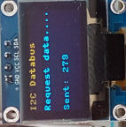
The Pico (Master) initiates communication to Address 0x0A. The Arduino, acting as a peripheral, triggers a hardware interrupt to push the latest sensor string onto the bus.
- Bus A (I2C0): Shared between the Arduino Slave and the primary system OLED.
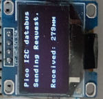
- Bus B (I2C1): Dedicated to a local status OLED on the Pico to prevent UI rendering latency from interfering with sensor requests.
During development, it was determined that the Arduino Slave cannot safely communicate with an OLED on the same databus while configured as a target. Attempting to initialize the display on the Slave side causes Interrupt Conflicts that hang the I2C bus. The solution was to delegate all display tasks exclusively to the Master node.
- Arduino: Constant polling of MaxSonar sensor data via analog/PWM input.
- Pico: Sends
readfrom(0x0A)command via the MicroPython I2C driver. - Handshake: Arduino
onRequestISR fires, transmitting the pre-calculated data packet. - Processing: Pico parses the telemetry and updates both OLED displays via separate hardware buses.
When bridging a 3.3V Pico and a 5V Arduino:
- Common Ground: Ensure the GND pins of both microcontrollers are connected. Without a shared reference, the SCL/SDA pulses will be unreadable.
- Logic Thresholds: While the 5V Arduino can often detect 3.3V logic as HIGH, a bidirectional level shifter is recommended for industrial reliability.
- Pull-up Resistors: External 4.7kΩ resistors to 3.3V are recommended for the shared bus to keep signal rise-times within I2C specifications.
© 2026 MatsRobot | Licensed under the MIT License