Lesson 8: Ambient occlusion
In previous lectures we used local illumination model. In other words, for computing illumination of a current pixel we did not take into account its neighbors. Phong reflection model is a famous example of such approach:
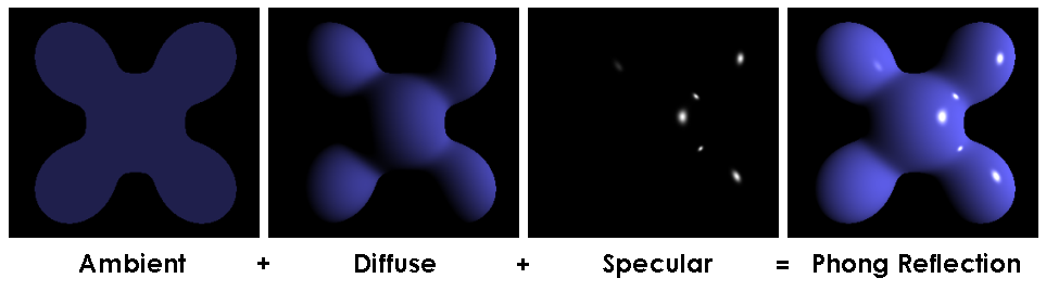
In this model final illumination intensity for a point is a sum of three components: ambient intensity, constant for all points in the scene, diffuse and specular highlights depending on normal vectors. Wait a minute, why did he choose constant ambient component?
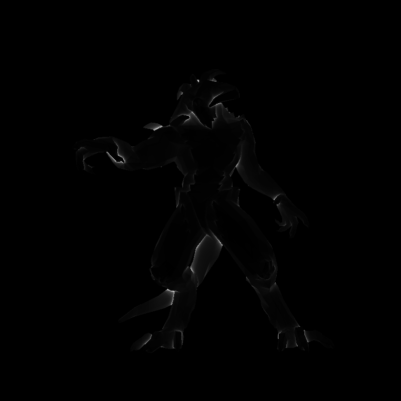
Well, I was not 100% right: we did use a bit global illumination when we computed shadow mapping. Let us check another possibility to improve our renders (note that one does not exclude another!). Here is an example where I used only ambient component of the Phong reflection model:

No diffuse component, no specular. Ambient only, however it is easy to see that I did not choose it to be constant. Okay, the problem is stated as follows: let us ambient intensity for each point of our scene. When we previously supposed constant ambient illumination, it means that we supposed our scene so nice that all light was reflected everywhere equally. A bit strong hypothesis that is. Of course, it was made back in the old days where computing power was severely limited. Nowadays, we can spend a bit more to get more realistic images. Global illumination is more expensive than the local is. Recall that for shadow mapping we were forced to do two-passes rendering, thus roughly dividing our FPS by 2.
The source code is available here. Let us suppose that our object is surrounded by a hemisphere, emitting light uniformly (cloudy sky). Then let us choose randomly, say, a thousand points at the hemisphere, render the object thousand times and to compute what parts of the model were visible.
Question: Do you know hot to choose uniformly a thousand points on a (hemi-)sphere? Something like this:
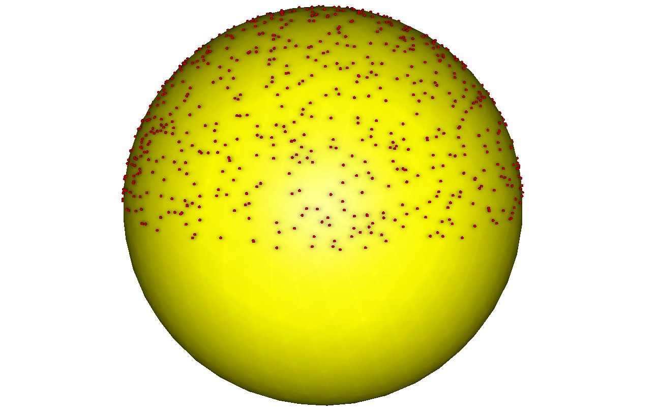
If we simply choose randomly a longitude and a latitude, we will obtain an accumulation of points near the poles, thus breaking our assumption on uniform lighting of the sky. Check the answer.
Question: where do we store the visibility information?
Since we are in the brute force section, then the answer is obvious: in a texture!
Thus, we do a two-pass rendering for each point we picked on the sphere, here is the first shader and the resulting image:
    virtual bool fragment(Vec3f gl_FragCoord, Vec3f bar, TGAColor &color) {
        color = TGAColor(255, 255, 255)*((gl_FragCoord.z+1.f)/2.f);
        return false;
    }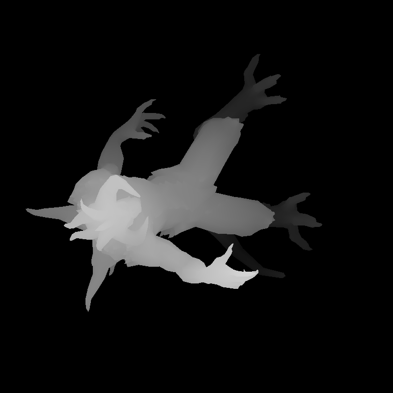
This image is not very interesting for us, we are more interested in its z-buffer, exactly as in the previous lesson. Then we do another pass:
    virtual bool fragment(Vec3f gl_FragCoord, Vec3f bar, TGAColor &color) {
        Vec2f uv = varying_uv*bar;
        if (std::abs(shadowbuffer[int(gl_FragCoord.x+gl_FragCoord.y*width)]-gl_FragCoord.z)<1e-2) {
            occl.set(uv.x*1024, uv.y*1024, TGAColor(255));
        }
        color = TGAColor(255, 0, 0);
        return false;
    }
The resulting image is not interesting either, it will simply draw a red image. However, this line I like:
occl.set(uv.x*1024, uv.y*1024, TGAColor(255));occl - is initially clear image; this line tells us that if the fragment is visible, then we put a white point in this image using fragment's texture coordinates. Here is the resulting occl image for one point we choose on the hemisphere:
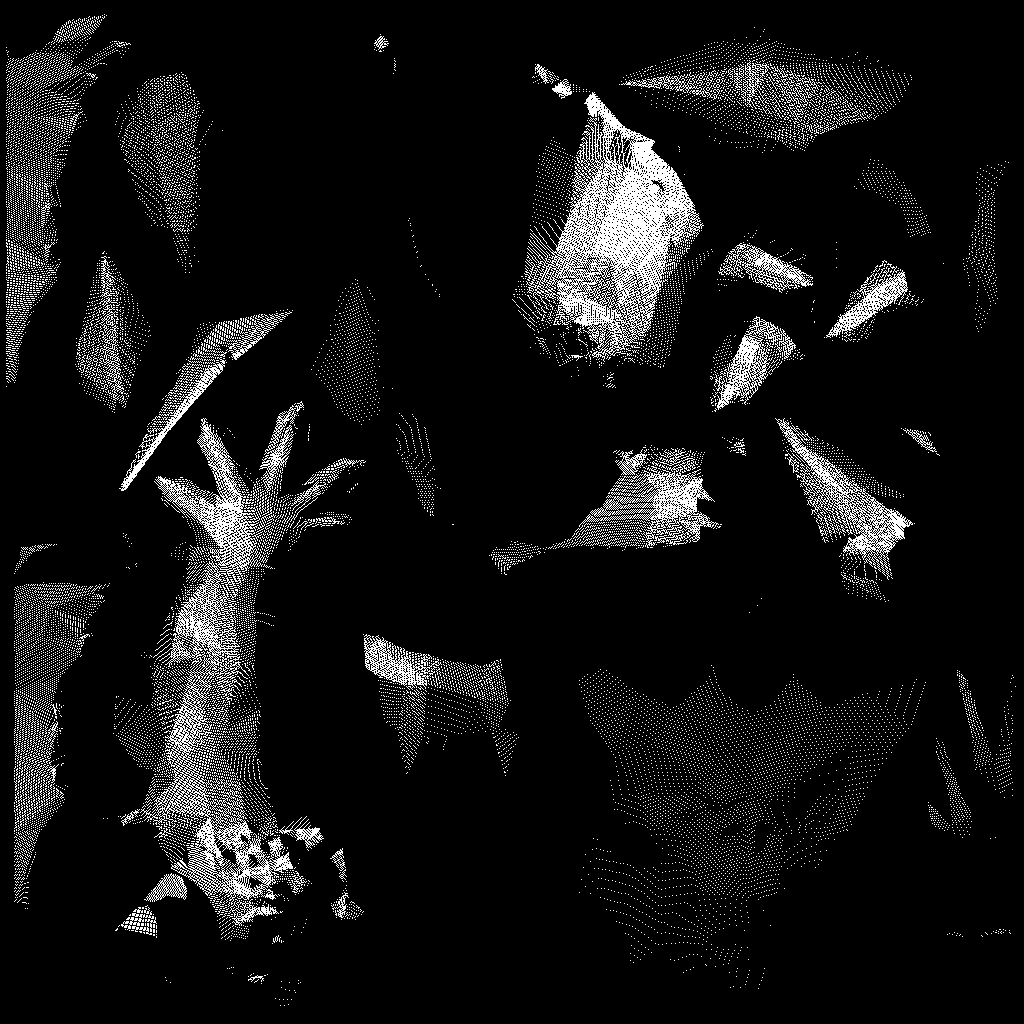
Question: Why are there holes in obviously visible triangles?
Question: Why are there triangles more densely covered than others?
Well, we repeat above procedure a thousand times, compute average of all occl images and here is the average visible texture:
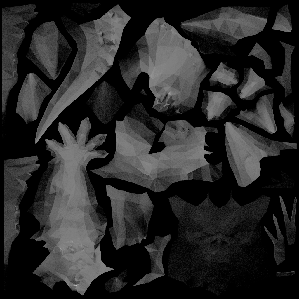
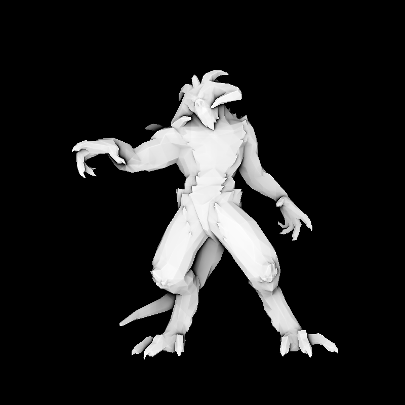
Cool, looks like something we could want. Let us draw our Diable without any lighting computation, simply by putting above texture:
    virtual bool fragment(Vec3f gl_FragCoord, Vec3f bar, TGAColor &color) {
        Vec2f uv = varying_uv*bar;
        int t = aoimage.get(uv.x*1024, uv.y*1024)[0];
        color = TGAColor(t, t, t);
        return false;
    }
Here aoimage is the above (average lighting) texture. And resulting render is:
Question: Wow, he is in a bad mood... Why?
This question is linked to the previous one. Did you notice that in Diablo's texture there is one arm only? The artist (in this case Samuel Sharit) is practical and did not want to waste precious resources. He simply said that the arms are textured in the same way and both arms can have same texture coordinates. Roughly it means that our lighting computing will count arms twice, thus quadrupling the light energy in the final render.
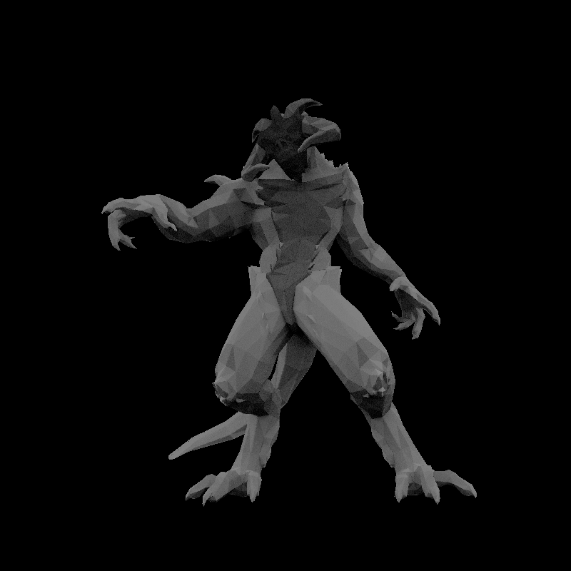
This method allows to precompute ambient occlusion for scenes with static geometry. Computation time depends on the number of samples you choose, but in practice it does not matter since we compute it once and use as a texture afterwards. Advantage of this method is its flexibility and ability to compute much more complex lighting than a simple uniform hemisphere. Disadvantage - for doubled texture coordinates the computation is not correct, we need to put some scotch tape to repair it (see the teaser image for this lesson).